|
|
Hi Sean I update to the new item list for SWAN. I try to search which new items are needed for drawing schematic and PCB artwork. and I'm gathering the datasheet and information. please see the attached file. and update your comment. |
|
|
Hi, SB I provide two PCB dimension for you reference. One is new design which you provide to us. Another one is original design which reduced the PCB width. Thank you. |
|
|
Hi Sean. Tom I'm reviewing the docs. but the DDR block is changed. If SoC's vender confirmed this placement of DDR. Please update Soc's confirmation. |
|
|
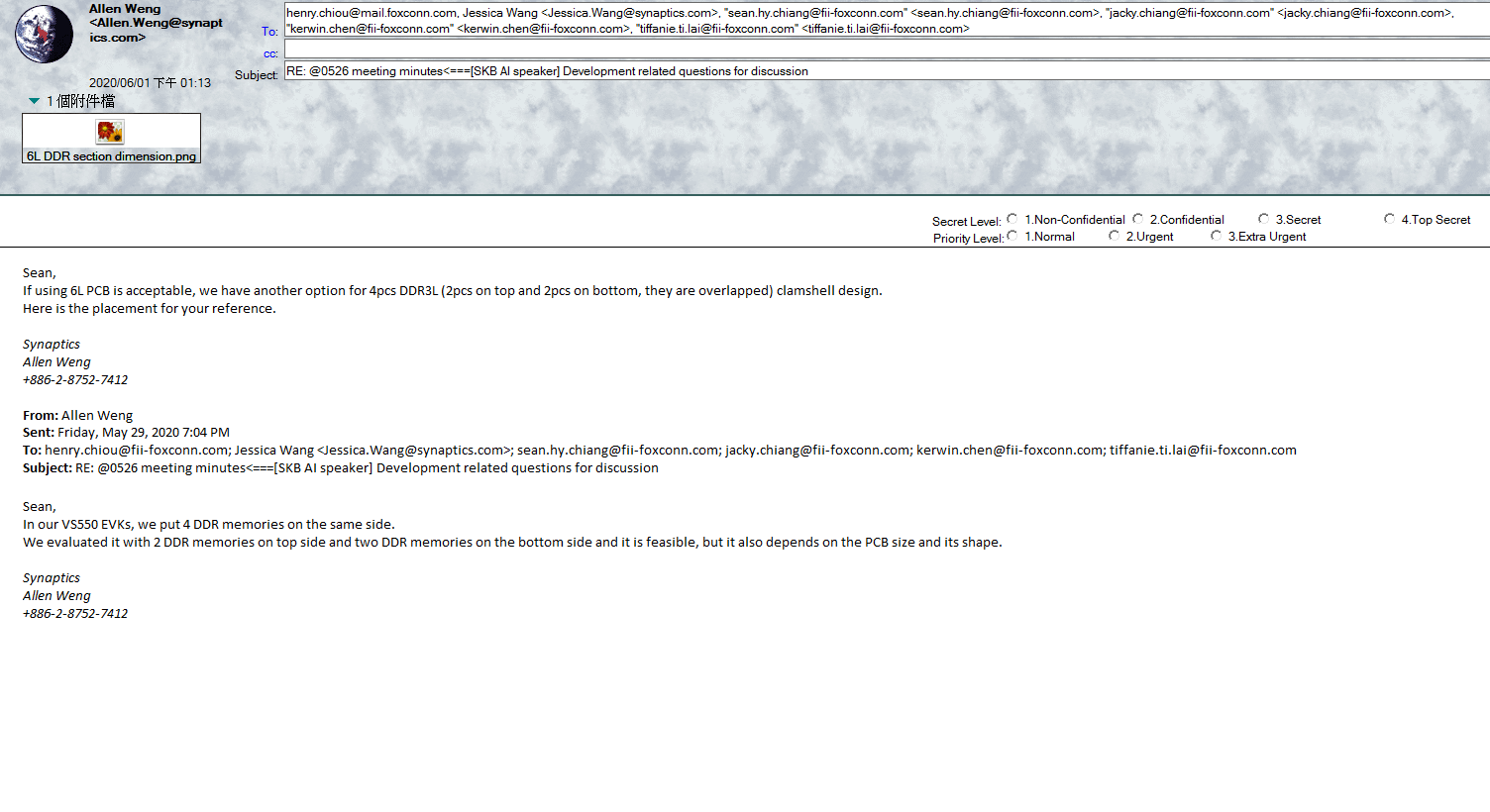
Hi SB, Please find attached for the picture of the DDR layout option captured from Synaptics FAE email. email about DDR design.png (86,585 bytes) |
|
|
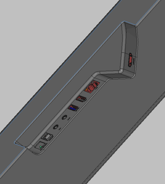
Hi Sean I have some questions 1. Mic PCB 1) SKB manager asked me that FII can design to MIC pcb with some curve (see the below picture) is it possible curved design is not fixed, but they said curve shafe may has better performance for side FFV 2. IO port design 1) SKB gave me to design ID but they designed that HDMI port has a 45 degree angle (see the below picture and attached files) 2) Can you design the pcb with SKB's design ID? Mic_pcb_curved.gif (17,672 bytes) location_IOport_Swan.gif (18,135 bytes) |
|
|
Hi Sean Sorry. the design ID which HDMI has a 45 degree angle is canceled. I'll update another 3d rendering. |
|
|
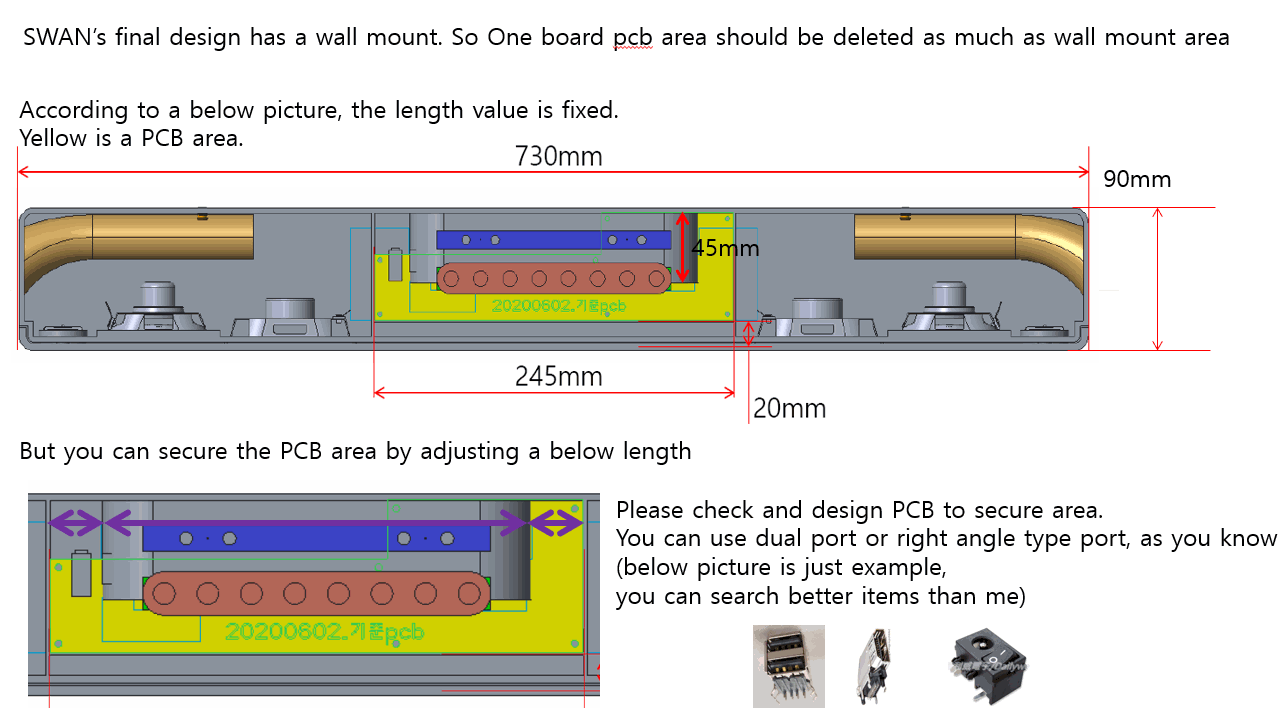
Hi Sean SWAN has a wall mount. so you should layout pcb considering the wall mount area I update INKEL's 3d rendering and 2d drawing document. see the attached file. and update your comment and PCB Size document Swan_design_withwallmount.gif (72,123 bytes) |
|
|
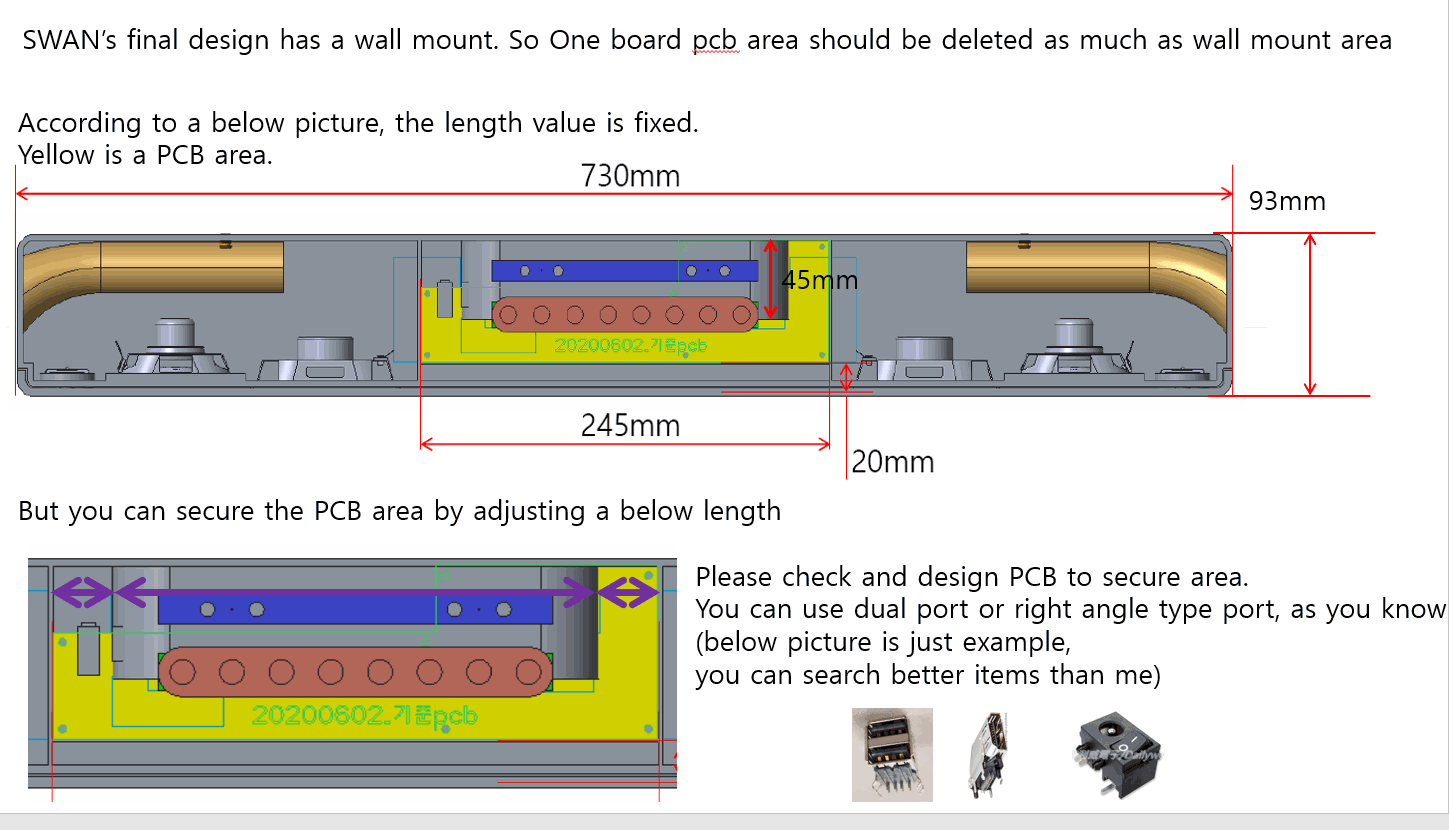
Hi Sean I update gif file again. the SWAN size is 730x93x60 Swan_design_withwallmount-2.gif (86,234 bytes) |
|
|
Hi Sean I update the amp schematics. |
|
|
Hi SB, From your gif drawing, it's too rough to confirm PCBA size. I will have our ME & HW RD to review the final 3D and reply you our evaluation by tomorrow. By the way, I was wondering who will decide the case size? It should not be decided by Inkel alone, right? Therefore, why the housing size is fixed without FXN's confirmation? And please note that this is not a pure sound bar product but an OTT plus sound bar. So, we should consider that some space will be needed to place OTT related chipset, I/O and circuits. |
|
|
Hi SB, For MICs acoustic design, I would like to raise an issue is that the ATV Google assistant only required 2 MICs processed using GVA S/W. Therefore, if SKB required 4 MICs design, it will conflict with Google's requirements. I think we should discuss with SKB first to determine the number of MIC first. As you know, it will also affect the ID/ME/HW design. |
|
|
Hi Henry I update my commnent at below --------------------------------------------------------------------------------------------------------------------------------------------------------------- Hi SB, From your gif drawing, it's too rough to confirm PCBA size. I will have our ME & HW RD to review the final 3D and reply you our evaluation by tomorrow. [SB 0604] If you want to more information, please let me know detail. I ask Inkel to your request. By the way, I was wondering who will decide the case size? It should not be decided by Inkel alone, right? Therefore, why the housing size is fixed without FXN's confirmation? And please note that this is not a pure sound bar product but an OTT plus sound bar. So, we should consider that some space will be needed to place OTT related chipset, I/O and circuits. [SB] That's right. case size was decided by SKB. and I have updated many information for housing and case size at mantis 832, 840. and asked you to pcb size and risk many time. you can suggest your guide |
|
|
Hi Sean this is very important issue. could you please give ALT to official mail for MIC design? ---------------------------------------------------------------------------------------------------------------------------------------------------------------------------------------------------- Hi SB, For MICs acoustic design, I would like to raise an issue is that the ATV Google assistant only required 2 MICs processed using GVA S/W. Therefore, if SKB required 4 MICs design, it will conflict with Google's requirements. I think we should discuss with SKB first to determine the number of MIC first. As you know, it will also affect the ID/ME/HW design. |
|
|
Hi SB, Please find attached for our PCBA size accessment based on the latest 3D of SWAN. We have added some comment on page 4~6. Please review it and let us know your thought. We can have further discussion at the meeting next Monday. Thanks. |
|
|
Hi SB, Based on our discussion with Inkel at yesterday's meeting, here is our recommendation for PCB and case size. We have also attached a 3D PCB stacking for your reference. Please check it and see if you have any further questions. |
|
|
Hi Sean What is the password of "swan_pcb_assembly-20200609.7z", this file is locked |
|
|
Hi SB, The password is "123456" |
|
|
Hi Sean I update the version up Audio Amp schematics And Dreamus (which will design the SKP and Amp) request to schematic for debugging 1. I2C line can be opened Between Soc and Audio amp (they will rework wiring to tune Sound) 2. SPK impedance is 4 ohm, please check the output is 20W and 40W. |
|
|
Hi Sean I update the connector information of SPK. yeon-ho locking type. (see the attached excel file) |
|
|
Hi Sean I update the DC jack specification. please see and apply it to the schematic |
|
|
Hi SB, It looks SKB use the different type of DC jack than the Eagle project. If SKB still need the extraction force to meet 1.8kg/f in SWAN project, why don't we use the same one as Eagle? |
|
|
Hi Tom, Please check the updated AMP schematics and connector info. of SPK provided by SB. |
|
|
I update my comment the below your sentence. --------------------------------------------------------------------------------------------------------------------------------------------------------------------- It looks SKB use the different type of DC jack than the Eagle project. [SB] Yes, that's right If SKB still need the extraction force to meet 1.8kg/f in SWAN project, why don't we use the same one as Eagle? [SB] The criteria is over 1.4Kg/f If the same dc jack, the user in field can connect to other device which has a low voltage. to prevent demage, SKB decided to different dc jack. |
|
|
Hi SB, Could you please update the key board, LED board size inside the housing? And we would like to define the LED scenario, we are searching LED driver solution. Could you please provide LED scenario defination for us? Thank you. |
|
|
Hi, SB According to "Yeonho_SMH-250-NN.XLSX", SWAN project select "SMH250-06" as Speaker connector. This means that six speakers which total six signals are connected to this connector, right ? Please provide pin define of this connector and note pin 1 position. Could you provide the PCB side connector drawing ? Thanks ! |
|
|
Hi, SB About DC Jack, because "SIMULA" is not Foxconn QVL vendor. So, we can't use this DC Jack directly. But we can use alternative material from Foxconn QVL vendor. Do all dimensions of the alternative material must the same as "SIMULA AJ296B-3100-412" or just meet DC plug dimension ? Thanks ! |
|
|
Hi Tom Lee I update my comment FII can develop the DC jack with Your vender. and You must be followed the SIMULA AJ296B-3100-412 spec. ---------------------------------------------------------------------------------------------------------------------------------------------------------- Hi, SB About DC Jack, because "SIMULA" is not Foxconn QVL vendor. So, we can't use this DC Jack directly. But we can use alternative material from Foxconn QVL vendor. Do all dimensions of the alternative material must the same as "SIMULA AJ296B-3100-412" or just meet DC plug dimension ? |
|
|
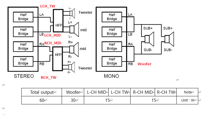
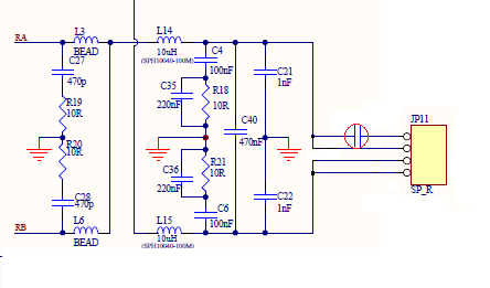
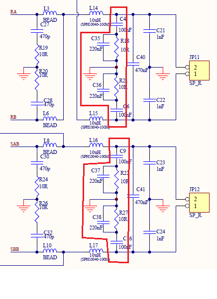
Hi Tom Lee I update vender's request. 1. the connector should be used 4 pin connector for tweeter, mid range, and woofer (see the attached file "HPF.PNG") 2. the serial cap should be needed at tweeter HPF block (see the attached file "HPF.PNG" and the cap location is in red circle nearby the 4pin connector) - The vender suggested "GRM32ER71H475KA88L" and the rated voltage should be over 40V. 3. I2C line can be opened Between Soc and Audio amp (they will rework wiring to tune Sound) _ I already mentioned it 4. I update the PCB Layout guide of Audio amp. ------------------------------------------------------------------------------------------------------------------------------------------------------------------------------------ Hi, SB According to "Yeonho_SMH-250-NN.XLSX", SWAN project select "SMH250-06" as Speaker connector. This means that six speakers which total six signals are connected to this connector, right ? Please provide pin define of this connector and note pin 1 position. Could you provide the PCB side connector drawing ? HPF.PNG (15,228 bytes) |
|
|
Hi Mr.Yoon and SB, Here is the updated block diagram of SWAN. FYR. |
|
|
Hi, Yoon Because I2S and PDM of VS-550 are Multiplexing. Could you provide the scenario of AUX input, MIC input and Digital microphone input for us ? Thanks ! |
|
|
Hi Yoon, As I mentioned yesterday, we found that the PDM and I2S_Data input are multiplexing. So the original architecture will not works. Therefore, we have discussed with Synaptics about this issue and update again the block diagram as attached. And the audio block diagram will be similar with AI2. |
|
|
Hi, SH SON I jot the DC jack datasheet, PLS help to review it. Thank you ! Regards, Tom |
|
|
Hi, SH SON For wire to board connector of MIC board, LED board and keypad board. I attached the datasheet for you reference. Please help to review it. Thanks ! Regards, Tom |
|
|
Hi Tom, Please also provide the datasheet of connector of audio AMP to SH for checking. Dreamus have to prepare the sample for EVT build until end of this month. |
|
|
Hi Tom and Please let us know below - full part number of connector MIC b/d, LED b/d and Keyborad b/d - cable (or wire harness) datasheet and full part number Sean. Please let us know the full part number of header(Amp side) and connector (PCBA side) And the Dreamus will be designed the pin map as attached file. If you have any changed, please share your designed pin map. Thanks SON |
|
|
Hi, SH Part number are as below. MIC b/d and Keyborad b/d: HSM1101-L1200-9H LED b/d: HSM1081-L1200-9H Thanks! Tom |
|
|
@ TOM Thanks connector part number, please applied this connector each pcba 3d modeling data. @Shen Could you please send the audio amp block schematic? because we are checking with b&o about audio performance THanks SON |
|
|
Hi, SH The audio class-D amplifier schematic had finished. I attached it for you reference. I have some questions: 1. Are HPF design correct or uncorrect ? 2. For L803, L805, L810~L813, because PCB size limitation. Can I reduce inductor rating current value ? |
|
|
Hi Emma, The vendor modified the file based on the their advice. Plz let me know if any comment. |
|
|
@Tom Lee, Could you provide inductor "L803, L805, L810~L813" full part number and datasheet? because it is critical part for audio performance and Dreamus need to check inductor characteristic. Thanks SON |
|
|
Hi, SON The datasheet of "L803, L805, L810~L813" as attached. Vendor: CHILISIN, P/N: MHCC10040-100M-R7. Thanks ! Tom |
|
|
Hi Tom and Sean Here is update SPK unit pin map. if you have any question, please ask me. Thanks SON |
|
|
Hi, SON I delete 0ohm/0805 resistors at pin 1 of J803 and J804 following your suggestion. I also follow ESMT TW suggestion that remove some resistors and capacitors at HFP (AD83586B_remove RC at HPF. png) I update the amplifier schematic, PLS help review it. Thanks ! Tom AD83586B_remove RC at HPF .png (34,740 bytes) |
|
|
Hi Tom and Sean also need to apply inductor LS communicaction "sph10040-100m" for "L803, L805, L810~L813" - 10uH / 7.8A (Heat Rating Current) don't apply heat rating current 6.5A. this part is also sound tuning parts this block already verified and tested circuit. Dreamus don't want to change value and part manufacture. please refer to the attached email that is test result. Thanks SON |
|
|
Hi SH, Update system power tree based on 90W speakers for noraml&max. system power |
|
|
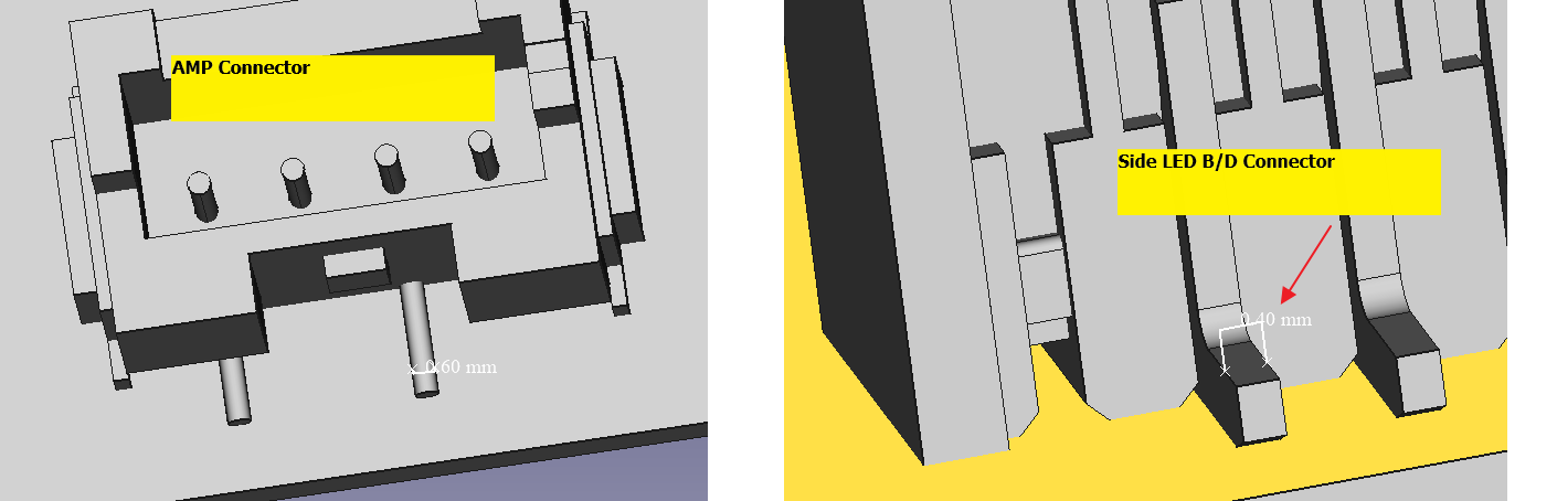
Hi Sean As a result of reviewing the led board, back data of connector selection is required. https://mantis.cnsbg.foxconn.com/vaas/view.php?id=847#c3748 The current LED sub b/d connector doesn't seem to be best choice. because 1. there is only function "Light on/off". no more need 8-pin cable required. it might be 4p cable is OK. 2. connector currnet rating is too high, - As contact pin width " 0.4mm" on 3d data. based on LED 19-137-R6GHBHC-S1906-2T dataheet : Pd (= R6 60mW + GH 95mW +BH 95mW = 250mW ) * 2 = 500mW = 100mA It would be okay to use a smaller pin width. Action item 1. Review 4 pin connector at right angle type. 2. Share the datasheet " HSM1081-L1200-9H_ASM" If you need to keep your current design, Please present Evidence why applied 8pin & 0.4mm pin width connector Thanks SON connector.png (33,797 bytes) |
|
|
Hi Fu-Chiang, Please check following questions from SH and reply asap. The current LED sub b/d connector doesn't seem to be best choice. because 1. there is only function "Light on/off". no more need 8-pin cable required. it might be 4p cable is OK. 2. connector currnet rating is too high, - As contact pin width " 0.4mm" on 3d data. based on LED 19-137-R6GHBHC-S1906-2T dataheet : Pd (= R6 60mW + GH 95mW +BH 95mW = 250mW ) * 2 = 500mW = 100mA It would be okay to use a smaller pin width. Action item 1. Review 4 pin connector at right angle type. 2. Share the datasheet " HSM1081-L1200-9H_ASM" If you need to keep your current design, Please present Evidence why applied 8pin & 0.4mm pin width connector |
|
|
Hi tom and Sean here is SKP unit pin map, this version is fixed until DVT sample. Thanks SON |
|
|
Hi Sean Please feedback No.1, and No.4 ---------------------------- First of all, I update the 3d modeling of SWAN only for PCBA area. https://mantis.cnsbg.foxconn.com/vaas/view.php?id=847#c3757 I think that thermal and BT antenna simulation can be possible. If you have any problem about 3d modeling data, please ask me. Also please see the below note. 1. It has still conflict on front side boss area. : Each boss area need to cut PCB about 4mm. : PCB layout should be fit the bfx_ua300_asm_thermal_2007141230.stp mechanical data : If pcb layout is not possible, please report that problem with artwork layout evidence I know it is hard to layout the pcb. But the mechanical design proceeds according to the final design. As you know it cannot be modified. 2. LED PCBA middle connector can’t insert at this time. This issue will be handle next release. : this is relate “1. Boss area” issue”. After the “1. Boss area” issue is cleared, it will be solve it. 3. If the thermal simulation result show a high temperature, Foxconn thermal engineer can be add more vent hole below area. The other surface are not considered at this time. A. Front side wall area B. PCBA bottom surface 4. IR performance : The distance from the front side and IR sensor is 20 mm. : In our experience, It is not a good location for performance. It is FXN responsibility to ensure IR performance. : We highly recommend that move the IR sensor to Front LED PCBA. : also next, modifying the mechanical design may hard to change. |
|
|
@Sean I update the LS communication inductor "sph10040-100m" Please refer to the characteristic and recommend PCB pattern. Thanks SON |
|
|
Tom, Please check attached Inductor datasheet requested by Dreamus. |
|
|
@Sean. About Mic sealing of knowles SPH0687LR5H-1. as SY,Yoon requested, please request Mic sealing guide to the knowles. and share to us. it is critical part on voice input signal, and also It may have impact mechanical design. SKT has its own guide, we have to consider both (SKT and knowles) guide. Thanks SON |
|
|
Hi, SON Because PCB size limitation, original connectors of speaker and sub-board can overlay inductor and eMMC flash. So, I would like to changes these connectors. Please help to review it. Speaker: 1. B4B-EH-A (PCB side connector, PLS see page 2) 2. B4B-XH-A ((PCB side connector, PLS see page 3) Sub-Board: 1. HS6108E (LED board) 2. HS6110E (MIC and keypad board) Thanks ! |
|
|
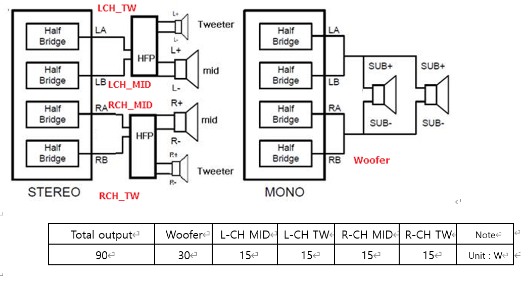
Hi Sean. Revise below link from SB, AMP load conditions https://mantis.cnsbg.foxconn.com/vaas/view.php?id=832#c3611 Please see the attached image and table Thanks SON SPK Unit_Load condtions_20200715.png (196,919 bytes) |
|
|
@Sean I update the Sound aging test spec : reference : SKB AI100. 1. Setting A. Source Device : Sine wave 1KHz. B. Vpp is depend on output level. Use this formula P=V^2/R C. Power Amp setting : 80% of maximum output. : in maximum 90W case, Set the output value to be 72w. 2. Play the music on youtube music A. Setting audio quality High : Youtube music “bitrate set to 256kbps AAC" B. Top 100 Songs Global i. https://music.youtube.com/playlist?list=PL4fGSI1pDJn6puJdseH2Rt9sMvt9E2M4i C. KPOP 2020 to 2021 ♫ Korean Pop Songs 2020 to 2021 (KPOP Playlist) i. https://music.youtube.com/playlist?list=PL4QNnZJr8sRNKjKzArmzTBAlNYBDN2h-J D. 100 Classical Music Pieces i. https://music.youtube.com/watch?v=K3He_GSvFzY&feature=share 3. Play continuously for 120 hours. 4. test criteria A. There should be no change in appearance. B. It should be functionally OK after aging test. if you have any question, please let us know. Thanks SON |
|
|
@ Tom LEE reply 0000840:0003766 I reviewed Speaker connector. this connector is not applicable for 20 AWG wire. I send the email Sean and Tom. Please see the attached email. Thanks SON |
|
|
Hi, SON I update the amplifier schematic, PLS help review it. Difference between this version and old version are 1. Delete 0ohm/0805 resistors at pin 1 of J803 and J804 following your suggestion. 2. Changes description (10uH/7.8A SPH10040-100M) of L803/L805/L810~L813. I also follow ESMT TW suggestion that remove some resistors and capacitors at HFP (AD83586B_remove RC at HPF. png) I have a question is that woofer connector (J802) only connect to woofer speaker. Why need to add a 4.7uF capacitor at pin 4 of J802 ? Thanks ! Tom AD83586B_remove RC at HPF -2.png (34,740 bytes) |
|
|
Hi Tom about DC jack review, there is not enough information to confirm this connector. https://mantis.cnsbg.foxconn.com/vaas/view.php?id=840#c3713 please update below information on the datasheet. 1. Detail specification : Electrical characteristics, Mechanical characteristics, Durability, and soldering conditions 2. Circuit diagram pin map update 3. No information detail material specification : metal composition and thickness and Plating specification 4. No information recommend plug information. if you have any question, please let us know Thanks SON |
|
|
@Tom 0000840:0003772 just remind that the serial Cap C1354 and C1352 also sound part. it should be "GRM32ER71H475KA88L" as already comment to you (below matis) https://mantis.cnsbg.foxconn.com/vaas/view.php?id=840#c3684 Please let us know, C1354 and C1352 full part number /manufacture note. I will let you know schematic review until 7/17 Thanks SON |
|
|
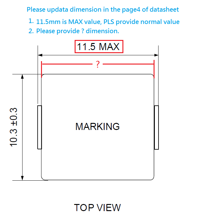
@SON reply 0000840:0003762 I am appling footprint, and the layout team reply that datasheet lack of some dimension. Please update datasheet. Thanks! FSP-20200715011-1.png (38,656 bytes) |
|
|
Hi SH and Philip, Please find the Knowles MIC design guideline as attached. By the way, Knowles can support us to review the MIC acoustics & sealing design to ensure the performance. Please check it and let us know if INKEL can release us the 3D data when they finished the design. Thanks. |
|
|
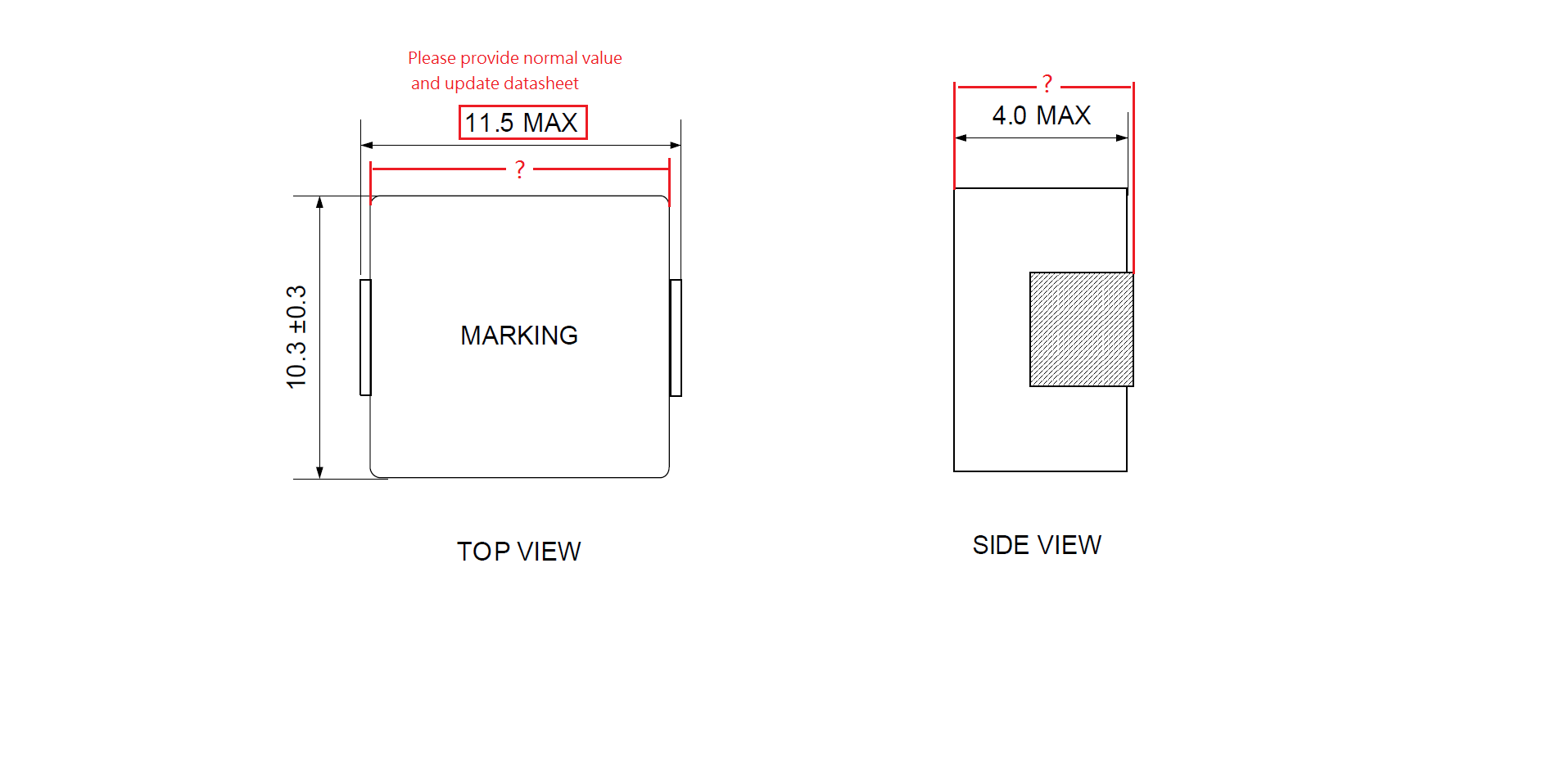
Hi Tom 0000840:0003784 Here is answer TOP VIEW : 10.3+-0.3 SIDE VIEW : 4.2 MAX 0000840:0003772 AMP schematic review result 1. Remove C1356. serial CAP only apply twitter SPK. 2. the other changes confirmed. Please update the schematic and send back again. THanks SON |
|
|
|
|
|
Hi, SON 0000840:0003784 Our layout team ask that new dimension must be update to datasheet. Please update new datasheet to me. 0000840:0003772 I remove C1356 in the schematic. Thanks ! Tom |
|
|
Hi Tom 0000840:0003791 1. Here is LS Inductor detail datasheet ---> Don't use this version datasheet. it has some typo, I will update again. 2. Please share the amp block schematic of removed C1356 Thanks SON |
|
|
@ SON reply 0000840:0003772 There are two vendors of current part number. 1. MURATA GRM21BR61H475ME51L 2. WALSIN 0805X475M500CT We can change to another part number which include murata "GRM32ER71H475KA88L". 1. Murata GRM32ER71H475KA88L 2. TAIYO UMK325B7475KM-P Thanks! |
|
|
Hi Tom 0000840:0003800 remind that, this part is also sound part, do not change Murata. Only use murata GRM32ER71H475KA88L. when you share the audio schematic, please record "C1354 and C1352" cap full part name value. Thanks SON |
|
|
Hi Tom reply 0000840:0003795 Please use this datasheet, it was fixed the typo from page 5 "Inspection Report" Thanks SON |
|
|
Hi, SON reply 0000840:0003801 I describe the vendor and part number of C1352 and C1354 in the schematic. Please see attached. Thanks. |
|
|
Hi Philip and SH, For the BT antenna, we recommended to use external PCB antenna and stick it on the inner side of front fabric cover. The RF performance such as return loss, peak gain and efficiency are meet our requirmenent. Please refer the simulation report as attached file. Also, our ME has defined the location and size in 3D drawing as attached. Please send it to INKEL review and let us know if there is any questions. Thanks. PW: 123456 |
|
|
Hi, SH reply 0000840:0003801 Murata GRM32ER71H475KA88L is EOL component. Could you please suggest alternative component or can we use original capacitor (MURATA GRM21BR61H475ME51L) ? Thanks ~ |
|
|
Hi, SH reply 0000840:0003744 I would like to update the SPK connector part number of eEH series. New P/N is B4B-EH(LF)(SN) which contact pin length is 4mm, original is 3.3mm (P/N: B4B-EH-A(LF)(SN) ). Others specification are the same. Please help to confirm SWAN project can use B4B-EH(LF)(SN) as SPK connector. reply 0000840:0003744 The pin 1 position of SPK connector following datasheet, right ? Thanks ! pin 1 of B4B-EH(LF)(SN).png (217,781 bytes) B( )B-EH-A-( ) (LF)(SN).png (93,778 bytes) B( )B-EH (LF)(SN).png (126,935 bytes) |
|
|
HI Tom Reply 0000840:0003813 original capacitor MURATA GRM21BR61H475ME51L is confirmed. Please apply MURATA GRM21BR61H475ME51L and update your schematic. Thanks SON |
|
|
Hi Tom Lee reply 0000840:0003766 0000840:0003818 First of all Change confirmed that 20 awg wire to 22 awg wire. So, we can use 22 awg connector. My understanding is that all three connectors of AMP are use only B4B-EH(LF)(SN) series. Is that right? At last time to change connector / housing in EVT. So pleas let us know Counterpart information on JST connector ASAP. J802 PN : Counterpart PN : J803 PN : Counterpart PN : J804 PN : Counterpart PN : Thanks SON |
|
|
Hi Tom and Sean Revise below AMP load conditions 0000840:0003768 Please see the attached image and table Thanks SON SPK Unit_Load condtions_20200722.png (90,873 bytes) |
|
|
Hi, SH reply 0000840:0003820 Yes, all three connectors of AMP are use only B4B-EH(LF)(SN). J802 PN : B4B-EH(LF)(SN) J803 PN : B4B-EH(LF)(SN) J804 PN : B4B-EH(LF)(SN) Thanks ! |
|
|
Hi, SH reply https://172.18.223.170/vaas/view.php?id=840#c3773 Vendor change the DC jack part number as SHD-6012D01-BLTN-T1. I attached the full datasheet for you reference. Thanks ! |
|
|
Hi, SH reply 0000840:0003820 0000840:0003827 The counterpart of B4B-EH(LF)(SN) are as below. 1. Housing : EHR-4 2. Contact : SEH-001T-P0.6 Thanks ! |
|
|
Hi, SH reply https://172.18.223.170/vaas/view.php?id=840#c3790 Our layout team ask that the datasheet must include dimension of body width and normal value of "body+pin". Please help update datasheet. Thanks ! FSP-20200715011-2.png (25,428 bytes) |
|
|
Hi Tom. Reply 0000840:0003828 Still need to update below information on the datasheet. 1. Material (Metal) thickness, plating thickness 2. Circuit diagram pin map update like 0000840:0003667 3. No information counterpart plug information. 4. not meet the Mating Force / Unmalting Force. -> based on RFP, unmalting force more than 1.4kg/F(10 time average). but this jack Unmalting Force is min 3N = 0.3kg/F Thanks SON |
|
|
Hi Tom Lee reply 0000840:0003840 I update the Inductor datasheet please see the attachment file Thanks SON |
|
|
@Sean, and Tom Please review and apply these requests before gerber out. 1. Internal support Boss 2. External Power switch center position adjustment 3. Please review the BT block move to front LED board 4. HDMI connector location. please see the attachment email more detailed. Thanks SON |
|
|
Hi SH, Reply 0000840:0003895 We will update you the main board 3D for item1&2 by today. For the item 3, we don't have enough space to place BT chipset and antenna in front LED board. Please see the details in my email sent by this morning. For the HDMI location, we will check and get back to you later today. Thanks, Sean |
|
|
Hi SH About the HDMI connector issue from Eagle, we will try to improve in SWAN. However we need to check with you if we will be using the same HDMI cable as Eagle? Because the spec of HDMI cable will affect the design... Best, Henry |
|
|
Hi SH, Reply 0000840:0003843 We have asked vendor to arrange the extraction force test and provide us the testing report first. Will update the schedule to you once we received report from vendor. Also we will ask vendor to evaluate the improve methods in parallel if the result is not good then. Thanks, Sean |
|
|
@Henry. reply 0000840:0003905 The SWAN accessory specifications are not finalized yet. But we will be using the same HDMI cable as Eagle. Please design based on Eagle HDMI cable @Sean Reply 0000840:0003912 Thank you for feedback about DC jack also, DC plug(counterpart plug) information is important for extraction force and ADP vender. Please remind update DC plug information Thanks SON |
|
|
@ SH reply 0000840:0003773 Update DC plug information in the datasheet, and attached report of "Mating / Unmating force test" and "Salt Fog test" for you reference. Thanks ! |
|
|
HI Sean and Tom SKB Designer ask that the each Side led white color can control color temperature? - color temperature range 1000K~10000K The LED scenario is under reviewing now, and If the color temperature can be controlled, The color temperature will be applied differently for each sound field mode. So, please let us know the side led color temperature can be controled at this HW (LED and LED Driver IC) design, Thanks SON |
|
|
Hi Fu-Chiang, Please check following request from SKB and get back to SH. ============================================================================ SKB Designer ask that the each Side led white color can control color temperature? - color temperature range 1000K~10000K The LED scenario is under reviewing now, and If the color temperature can be controlled, The color temperature will be applied differently for each sound field mode. ============================================================================ |
|
|
@Sean 0000832:0003712 please share the Elec cap data sheet. as your comment 3) Thermal review : Elecap information : Please share the datasheet ==> I will share the datasheet through the email. Thansk SON |
|
|
Hi Tom Reply 0000840:0003947 I checked vender test result. But the approval sheet still has not been updated (Min 3N). Please update the approval sheet? - 4.3 Unmating Force : performance 3N (Min.) Thanks SON |
|
|
Hi, SH Is the position of each speaker following attached picture ? Please help confirm. Thanks ! SWAN speaker position.png (130,320 bytes) |
|
|
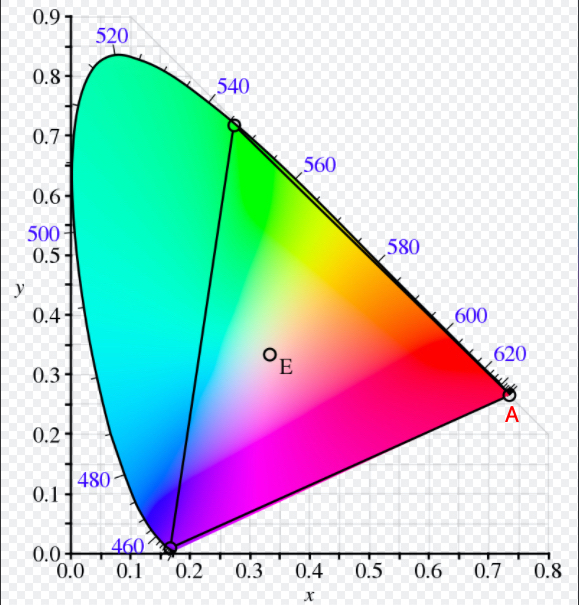
Hi SH, Please check following request from SKB and get back to SH. ============================================================================ SKB Designer ask that the each Side led white color can control color temperature? - color temperature range 1000K~10000K The LED scenario is under reviewing now, and If the color temperature can be controlled, The color temperature will be applied differently for each sound field mode. ============================================================================ We got the replied from LED vendor that due to the LED did not test color temperature, they cannot guarantee 1000K but can make sure the range of color temperature arount 1500K~10000K. According to CIE standard, 1000K of the color temperature for this LED material, the location will be at A. They are afried 1000K will over the triangle. But 10000K will be located at E of the central of CIE. So the vendor can guarantee color temperature is around 1500K~10000K. Thank you. |
|
|
Hi TOM reply 0000840:0003986 Confirmed position of each speaker as you attached picture Hi Fu-chiang Young Reply 0000840:0003995 Ok. My understanding is HW design side -> No problems that color can be set based on color temperature LED device side -> guarantee color temperature is around 1500K~10000K. due to 1000K is out of range CIE standard at LED spec Thanks SON |
|
|
Hi SH, Vendor said that they did not test color temperature, so on FXN side is also difficult to test color temperature. Maybe we can test RGB color with light pipe whether the color can be satisfied SKB or not when we can tune RGB function. Thank you. |
|
|
Hi Loonie and SH, Update block daigram of SWAN as attached. - Change the crystal of BT chipset to 40MHz. Regards, Sean |
|
|
Hi, SH reply 0000840:00003975 Update mate force and unmate force (item 4.2 / 4.3) in DC Jack datasheet. Thanks ! |
|
|
Hi Fu-chiang Young reply 0000840:0004003 Ok. I understand your concern. SKB designer is also want to check color with light pipe and additional, (SW) River is checked convert Color Temperature to RGB value by SW. 0000864:0004038 So, I will try to test working sample (light pipe) with convert SW. Thanks SON |
|
|
Hi SH, For EVT1 and EVT2 LED board, we made a mistake and cause the I2C conflict as AD82584F and LED driver LP5036. As well as that LED driver has 4 I2C address to change, so we need to rework U3_2 LED driver from 0x31 to 0x33. Please see attached file for rework sop document. MP had sent some LED board to ALT and may all need to rework. The SW team has verified the function and it could work for 0x33. Thank you. |
|
|
Hi Lonnie and SH, The main board rework SOP is as attached file. Thank you. |
|
|
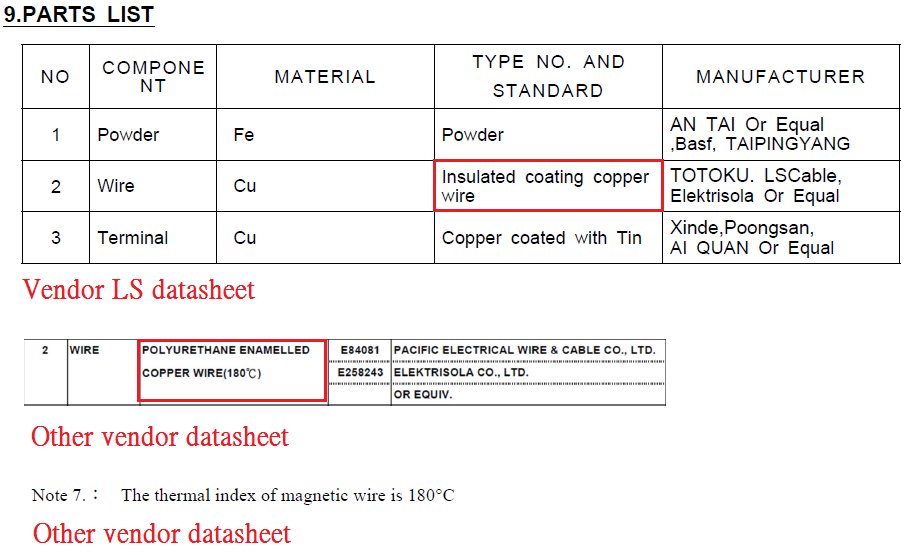
Hi, SH reply 0000840:0003886 Because the datasheet lack of temperature of "the thermal index of magnetic wire" . Please add this temperature in item9 of page9. Thanks ! inductor DS with the thermal index of magnetic wire.png (70,242 bytes) |
|
|
Dear Tom Please refer to attached documents Best regards Lonnie Kim |
- yk.jung ( (ALTech) Younkwang Jung ) developer

(SN).png)
B-EH-A-( ) (LF)(SN).png)
B-EH (LF)(SN).png)